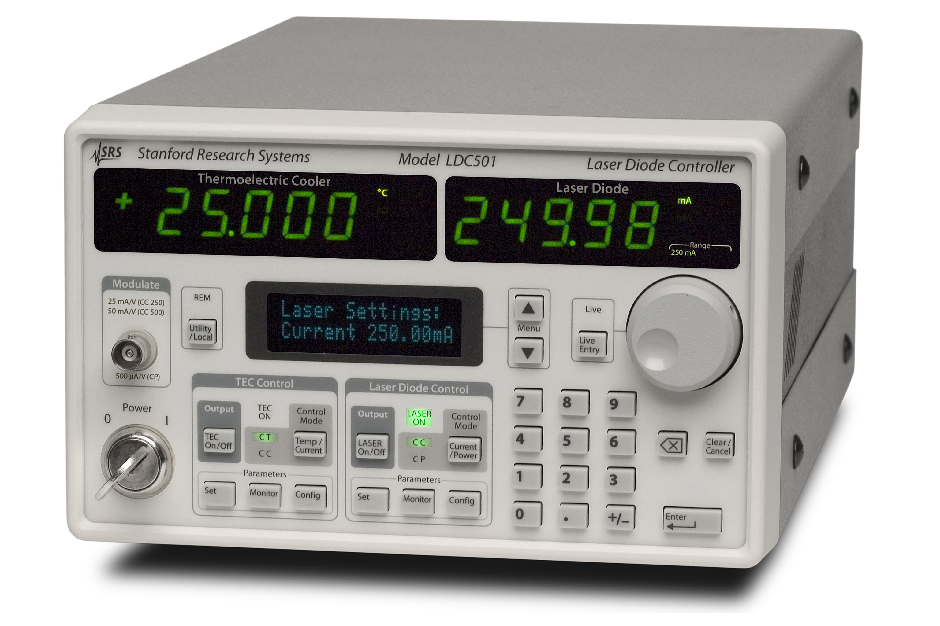
Home > Products > Scientific Instruments > LDC501


Laser Diode Controller
LDC501 — 500 mA laser driver, 36 W TEC controller

LDC500 — 100 mA laser driver, 36 W TEC controller

Laser Diode Controller
  • 100 mA or 500 mA current source
  • Ultra-low drift (<10 ppm/°C)
  • <0.3µA current noise
  • High bandwidth modulation (1.2 MHz)
  • Multiple laser protection features
  • Dynamic switching between CC and CP modes
  • GPIB, RS-232 and Ethernet interfaces

TEC Controller

  • 36 W output power
  • Ultra-high stability (0.0005 °C/°C)
  • <0.1 mA rms output current noise
  • Thermistor, RTD and IC sensors
  • Auto-tuning of loop parameters
  • Dynamic switching between CT and CC modes


Introducing the LDC500 SeriesLaser Diode Controller — highly stable, low-noise current sources, with an integrated temperature controllers — all at very affordable prices.

The LDC500 series are the ideal instruments for controlling the current and temperature of your laser diodes. They have the performance and features you expect from instruments costing twice as much. The LDC501 has up to 500 mA of output current with less than 1µA of rms noise, while the LDC500 has up to 100 mA of current and less than 0.3µA of noise.

With a low-noise current source, a 36 W high-precision temperature controller, and standard computer interfaces including Ethernet, the LDC500 series is the right choice for your laser diode testing and control applications.

Easy-To-Use Interface

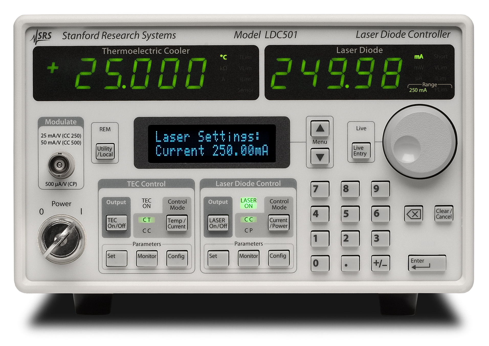
The LDC500 series have an intuitive user interface, and many first time users will be able to operate the instruments without having to crack open the manual (although we do recommend reading the manual). Unlike competitive models, the LDC500 series controllers have a dedicated front-panel display for parameter entry. You don’t have to sacrifice monitoring temperature or current to simply change an instrument setting — you have a separate two-line, blue alpha-numeric display for that. In addition, bright 5-digit green LED displays constantly monitor current and temperature, and are large enough to easily read from anywhere in the lab.

Laser Diode Protection

Multiple laser diode protection features, including slow start turn-on, adjustable current limits, and adjustable compliance voltage, keep your laser diodes safe when unexpected events occur. Fast clamping and shut down provide extra protection against intermittent contact with the laser. Combined, these features provide trouble-free, safe control of your laser diode.

Linear Power Supplies

Independent linear power supplies are used for the laser diode controller and the temperature controller. The supplies are designed with a magnetically shielded toroidal transformer, and provide ultra-clean, stable isolated power.

Computer Control

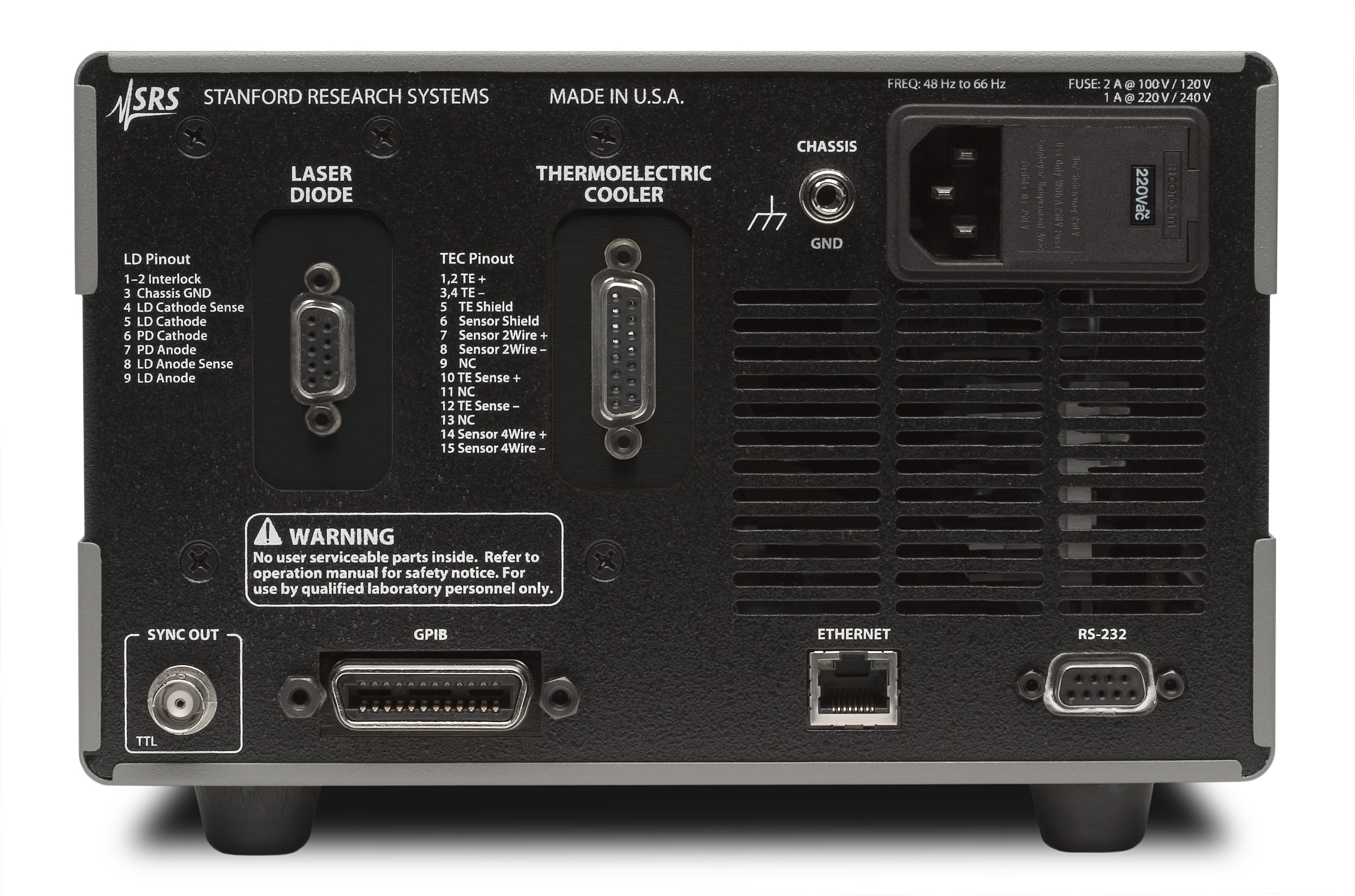
Remote operation of the LDC500 series is supported with GPIB, RS-232 and Ethernet interfaces. All instrument functions can be controlled and read over any of the interfaces. Up to nine complete instrument configurations can be saved in non-volatile RAM and recalled at any time. A TTL trigger output is also available to synchronize other test equipment.

Stable Laser Diode Controller

To ensure a stable optical output from your laser diode, the LDC500 series LD controllers were designed to deliver noise-free, precision operation. They are accurate to ±0.01 % FS, have automated testing setups, noise is as low as 0.2 µA rms, and they meet a drift specification of 10 ppm/°C.

The controller have two modes of operation for the laser diode: constant current and constant power. Constant current mode (CC) programs the source to a precise DC amplitude. Alternatively, the constant optical power mode (CP) servos the current source to maintain a constant signal on a monitor photodiode. Both control modes allow you to add an external modulation signal, with adjustable bandwidth up to 1.2 MHz (in CC mode) or 10 kHz (in CP mode).

Another convenient feature that the LDC500 series offers is a fully programmable photodiode bias voltage. You can set the bias between 0 and 5 V from the front panel, or remotely using one of the computer interfaces.

Bumpless Transfer

A unique feature of the LDC500 series is Dynamic “Bumpless” Transfer between CC and CP modes. This feature means you don’t have to shut down your laser to switch modes — simply press the Current/Power button.

36 W Temperature Controller

The LDC500 series integrated 36 W temperature controller lets you adjust temperature with 0.001 ºC resolution, and measure temperature with 0.01 ºC accuracy (with a calibrated sensor). It maintains a typical stability of 0.0005 ºC/ºC with respect to room temperature, and has a very wide temperature control range.

The TEC controller also has two modes of operation: constant temperature mode (CT) controls the TEC current to maintain a fixed temperature (or raw sensor value), while constant current mode (CC) operates the TEC at a fixed current. Thermistor, RTD and IC sensors are all supported.

The LDC500 serieshas an auto-tuning feature which automatically optimizes the PID loop parameters of the controller. Of course, full manual control is provided too. Dynamic "Bumpless" transfer between CT and CC modes for the TEC is also easy — just press the Temp/Current button.

Online Thermistor Calculator

About Thermal Stability

Temperature fluctuations in a typical laboratory environment can often exceed several degrees Celsius over the course of a day. Small temperature changes can mean significant current changes in your laser diode if your controller is not up to the task.

The LDC500 and LDC501 have a temperature coefficient of 10 ppm/°C, which is a factor of five better than competing models, making it the ideal controller for precision laser diode experiments.

The graphs to the right demonstrate the temperature performance of the LDC500. Over a 24 hour period, the ambient temperature change in the laboratory exceeds two degrees Celsius. Note that the output current deviation of the LDC after warm-up is stable to better than ±10 ppm.


Specifications

Laser Diode Current Source

Current Source

Range 0 to 500 mA, 0 to 250 mA (LDC501)
  0 to 100 mA, 0 to 50 mA (LDC500)
Setpoint 10 µA (LDC501), 1 µA (LDC500)
Accuracy ±0.01 % of full scale
Output impedance (DC) >1 MΩ
Stability  
     Thermal <10 ppm/°C
     Short term (1 hr.) <5 ppm full scale
     Long term (24 hr.) <15 ppm full scale
Noise (10 Hz to 1 MHz) LDC501
  4.5 µA rms (high range / high bandwidth)
  1.5 µA rms (high range / low bandwidth)
  2.3 µA rms (low range / high bandwidth)
  1 µA rms (low range / low bandwidth)
  LDC500
  0.9 µA rms (high range / high bandwidth)
  0.6 µA rms (high range / low bandwidth)
  0.5 µA rms (low range / high bandwidth)
  0.3 µA rms (low range / low bandwidth)
Compliance voltage  
     Range 0 to 10 V, programmable
     Resolution 10 mV
     Accuracy ±0.2 V
Current limit  
     Range 0 to 500 mA, or 0 to 250 mA (LDC501)
  0 to 100 mA, or 0 to 50 mA (LDC500)
     Resolution 10 µA
     Accuracy ±100 µA
Analog Modulation
Input range -10 V to +10 V
Input impedance 10 kΩ, typ.
Gain  
  LDC501
     CC mode 50 mA/V (LD current at high range), 25 mA/V (LD current at low range)
     CP mode 500 µA/V (PD current)
  LDC500
     CC mode 10 mA/V (LD current at high range), 5 mA/V (LD current at low range)
     CP mode 500 µA/V (PD current)
   
Bandwidth (-3 dB)  
     CC mode DC to 1.2 MHz (high bandwidth)
  DC to 10 kHz (low bandwidth)
     CP mode DC to 5 kHz (high bandwidth)
  DC to 100 Hz (low bandwidth)
Monitor Photodiode
Bias voltage 0 to 5 V, programmable
PD current range 0 to 5000 µA
Setpoint resolution (CP) 0.1 µA
Setpoint accuracy ±2 µA
Measurement & Display
Output current  
     Resolution 10µA (LDC501), 1µA (LDC500)
     Accuracy ±0.02 % FS
Photodiode current  
     Resolution 0.1 µA
     Accuracy ±0.02 % FS
Laser diode forward voltage  
     Resolution 1 mV
     Accuracy ±0.02 % FS ( 4 wire)


Temperature Controller

Temperature Control

Control range  
     IC sensor -55 °C to +150 °C
     Resistor sensor -150°C to +250 °C (10 Ω to 500 kΩ)
Setpoint resolution  
    Temperature 0.001 °C
    Resistance 0.1 Ω
Setpoint accuracy  
    Temperature 0.01 °C, sensor dependent
    Resistance ±0.1 % of sensor resistance
Stability (typ.) (using a 10 kΩ NTC thermistor)
     Thermal (vs. ambient) 0.0005 °C/°C
     Short term (1hr.) ±0.001 °C
     Long term (24 hr.) ±0.002°C
Control algorithm PID
Auto-tuning Step response
TEC Output
Source type Linear, bipolar current source
Current range -4.5 A to + 4.5 A
Setpoint resolution 1 mA
Setpoint accuracy ±5 mA
Max. power 36 W
Compliance voltage >8 VDC
Current noise (10 Hz to 1 MHz) <0.1 mA rms @ 1 A output, <0.2 mA rms @ 4 A output
Current limits  
     Range 0 to 4.5 A
     Accuracy ±5 mA
Temperature Sensors
Thermistors 10 Ω to 500 kΩ (10 µA, 100 µA, 1000 µA excitation)
RTD Pt-100, Pt-1000 (1 mA excitation)
IC voltage sensors LM335 and equivalent
IC current sensors AD590 and equivalent
Measurement & Display
Temperature  
     Resolution 0.001 °C
Thermistor  
     Resolution 0.1 %
     Accuracy 0.1 % ±0.05 Ω
TEC current  
     Resolution 1 mA
     Accuracy ±5 mA
TEC voltage  
     Resolution 1 mV
     Accuracy ±5 mV (4 wire)
General
Instrument connectors DB9-F (laser diode), DB15-F (TEC), BNC (modulate, trigger output)
Remote interfaces GPIB (IEEE-488.2), RS-232, Ethernet
Power 100 W, 100/120 VAC or 220/240 VAC, 50 Hz / 60 Hz,
Dimensions 7"× 5 " × 15" (WHL)
Weight 15 lbs.
Warranty One year parts and labor on defects in materials and workmanship


Stanford Research Systems, Inc. • 1290-D Reamwood Ave., Sunnyvale, CA 94089
Phone: (408) 744-9040 • Fax: (408) 744-9049 • email: info@thinkSRS.comwww.thinkSRS.com
© Stanford Research Systems, Inc. 2003