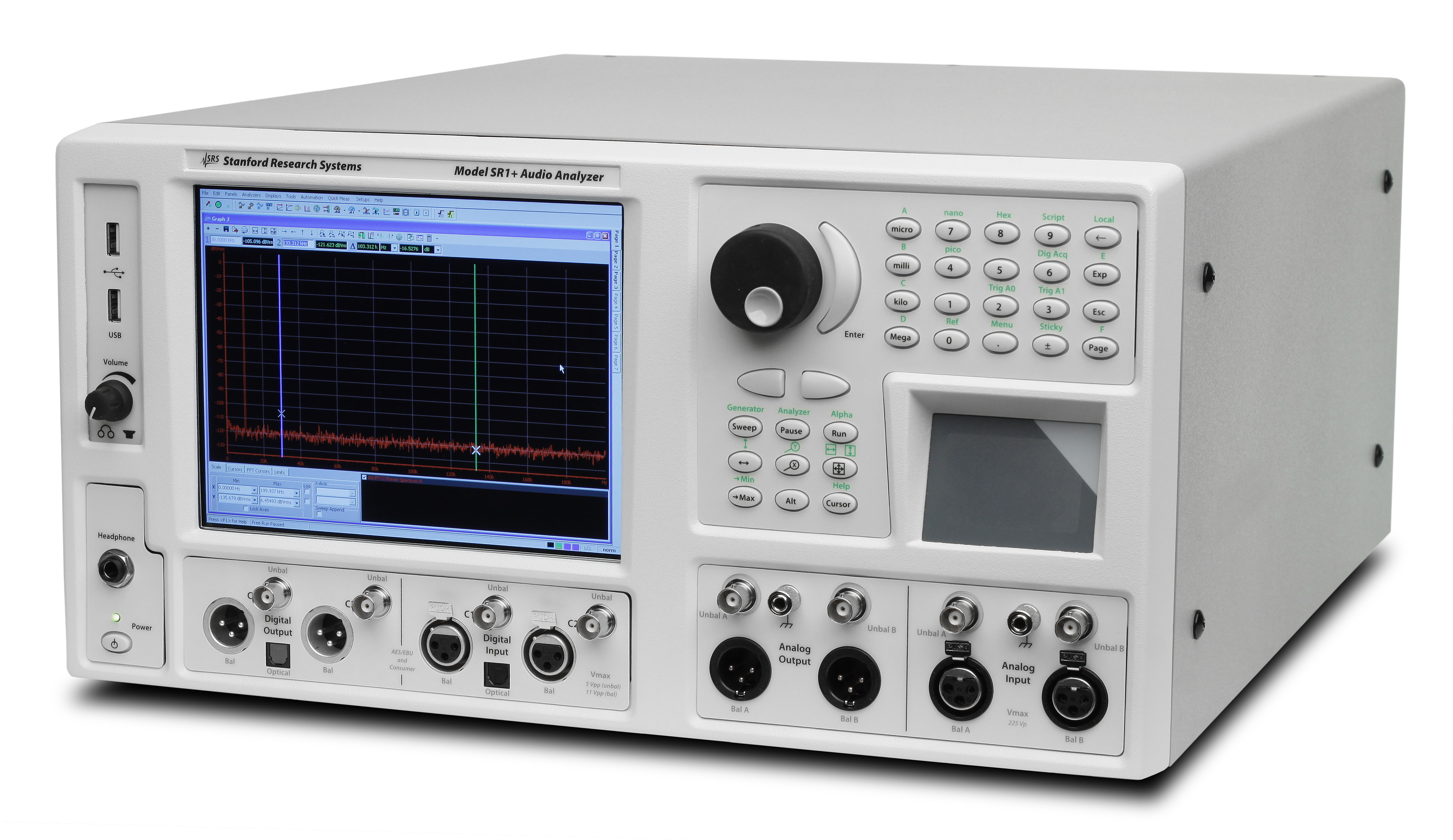
SR1 Audio Analyzer
Introducing SR1 Dual-Domain Audio Analyzer—a high performance audio analysis at a very affordable price.
SR1 Dual-Domain Audio Analyzer is a stand-alone instrument that delivers cutting edge performance in a wide variety of audio measurements. With a versatile high-performance generator, an array of analyzers that operate symmetrically in both the analog and digital domains, and digital audio carrier measurements at sampling rates up to 192 kHz, SR1 is the right choice for the most demanding analog and digital audio applications.
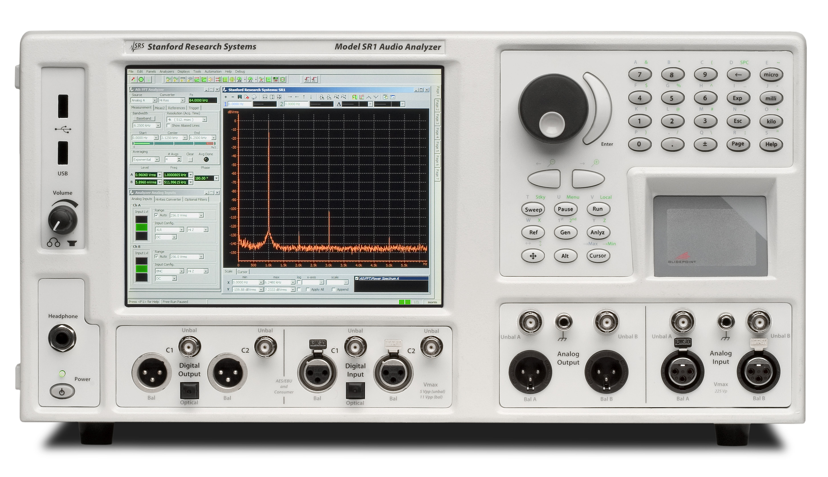
User Interface
SR1 uses an integrated computer running the Windows XP embedded operating system, so operation will be immediately familiar and intuitive. Depending on the application, SR1 can be operated with an external mouse and keyboard, or by using the front-panel knob, keypad and touchpad.
Seven on-screen tabbed pages are available for arranging panels, graphs, and displays. Screen setups, data, and instrument configurations can be quickly saved and recalled to either the internal hard disk or to a flash drive connected to one of the two front-panel USB connectors. An optional
While SR1's configuration panels offer total flexibility in setting up every detail of the analyzer, at times it is useful to get a measurement going quickly, without worrying about infrequently used parameters. That's where QuickMeas comes in. QuickMeas gives SR1 users the ability to get up and running on many common audio measurements such as Level, SNR, Frequency Response, and Crosstalk after answering just a few simple questions about the inputs and outputs of the DUT. When the measurements are finished, the results are available in a clear, easy-to-understand report.
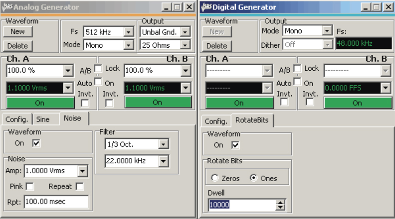
Analog Signal Generator
At the heart of SR1 is a uniquely flexible analog signal generator. All of the standard audio waveforms are available including sine, log-swept sine chirp, synchronous burst sine, noise (white, pink, and filtered), standard intermodulation test signals (SMPTE, CCIF, DIM), square waves, arbitrary waveforms (ASCII and .WAV), ramps and multitone waveforms. Many of these signals can be combined in the generator allowing you to create an unlimited number of test waveforms.
But the analog signal generator doesn't sacrifice performance for flexibility. With a flatness of ±0.008 dB (20 Hz to 20 kHz) and a residual THD+N of
Multitone waveforms with up to 50 tones, each adjustable in frequency, amplitude, and phase are calculated and loaded in real-time, without having to run a cumbersome off-line program to generate arbitrary waveform tables. A convenient FFT Chirp waveform is automatically synchronized to the FFT analyzer allowing instant FFT measurements of frequency response (magnitude and phase).
Digital Audio Signal Generator
The same flexibility and performance is found in SR1's digital audio signal generator. Almost all the same waveforms found in the analog generator are available in the digital generator with the addition of several special digital test waveforms including digital constant, walking bits, and a staircase waveform (for D/A testing).
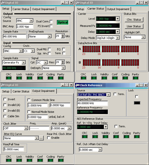
The digital audio output sampling rate is continuously adjustable from 24 kHz to 216 kHz (single and dual connector). Full control over transmitted status bits (in both professional and consumer formats), user bits, and validity bits is provided.
For digital interface testing, a variety of impairment signals can be imposed on the digital audio carrier. Carrier impairments include variable rise time (5 ns to 400 ns), common mode sine waves, normal mode noise, and several jitter waveforms (sine, square, and noise).
Timebase
All of SR1's sampling clocks are derived from an internal timebase with 5 ppm accuracy. For the most demanding applications, an optional atomic rubidium (PERF) timebase is available with an accuracy at shipment of
Analyzers
The heart of SR1's measurement abilities is its versatile set of analyzers which operate symmetrically on both analog and digital audio signals with no need to purchase additional options. Up to two analyzers can be run simultaneously on either the analog or digital inputs.
The Time Domain Detector makes all of the standard audio measurements including Amplitude, Crosstalk, and THD+N. Continuously variable bandwidth limiting and standard weighting filters are included. The post notch-filter distortion signal can be fed to an FFT analyzer for a live spectral display of distortion, or to the rear-panel monitor output or speaker.
The Single-Channel FFT and Dual-Channel FFT Analyzers offer live spectral displays with full zoom and heterodyne capability. The full resolution of the analyzer can be applied to any frequency range down to 1/512th of the full measurement bandwidth, leading to an effective resolution of
The two-channel FFT analyzer offers true single-shot frequency response measurements for the ultimate in accuracy. SR1 also has a complete set of impulse response measurements including impulse response, quasi-anechoic frequency response, and energy
The THD Analyzer makes frequency selective THD measurements on two user-selectable sets of up to thirteen harmonics of the input signal.
The IMD Analyzer makes standard audio distortion measurements including SMPTE, CCIF, and DIM. Frequency selective analysis ensures high measurement accuracy.
The Histogram Analyzer displays live histograms of input signal amplitudes and probability distributions. Realtime fits to Gaussian distributions can be generated.
The Multitone Analyzer, in combination with the Multitone Generator, can be configured to make fast single-shot measurements of a variety of audio parameters including Level, Frequency Response, THD+N, THD Total Distortion, Noise, Crosstalk, and IMD.
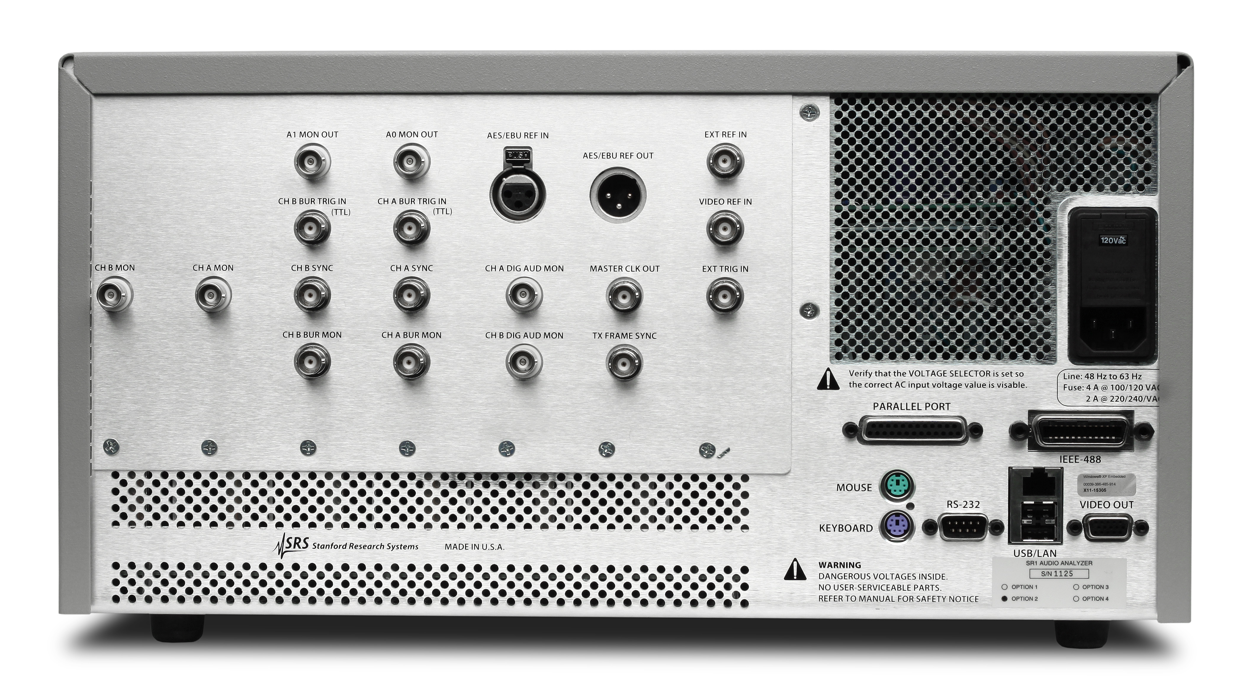
Digital Audio Interface
SR1 provides a complete set of measurements for digital interface testing. Carrier level and sampling frequency are measured directly. Status bits are fully decoded in both professional and consumer formats, and user bits are displayed as well. SR1's Jitter Analyzer measures jitter in both the time and frequency domain, including continuously variable bandwidth limiting and weighting in both domains. For frequency domain measurements, live zoomable and heterodyned spectral displays of jitter are available. Using the jitter chirp waveform, you can characterize jitter transfer functions in under a second. With a residual jitter of only 600 ps, the performance of SR1’s jitter analyzer is unbeatable.
Digitizer
An optional 80 MHz transient digitizer (opt. 01) provides additional digital audio carrier analysis. Operating on a record of up to 2M samples, the digitizer computes and displays the time record of the input signal and its jitter, input spectrum, jitter spectrum, and the probability distributions of the input and jitter amplitudes as well as the pulse width and pulse rate. Full color eye-diagrams can be generated allowing easy testing against user-configurable eye limits.
Automation and Programming
SR1 offers unprecedented flexibility for user scripting and remote programming.
Learning Mode
Learning mode is a powerful tool for quickly creating scripts without detailed knowledge of the programming environment. SR1 creates a script by recording each keystroke or user operation, and then converts the script to a VB script of Jscript program. These programs can be saved and edited like any other script, then run in the future.