


 (408) 744-9040
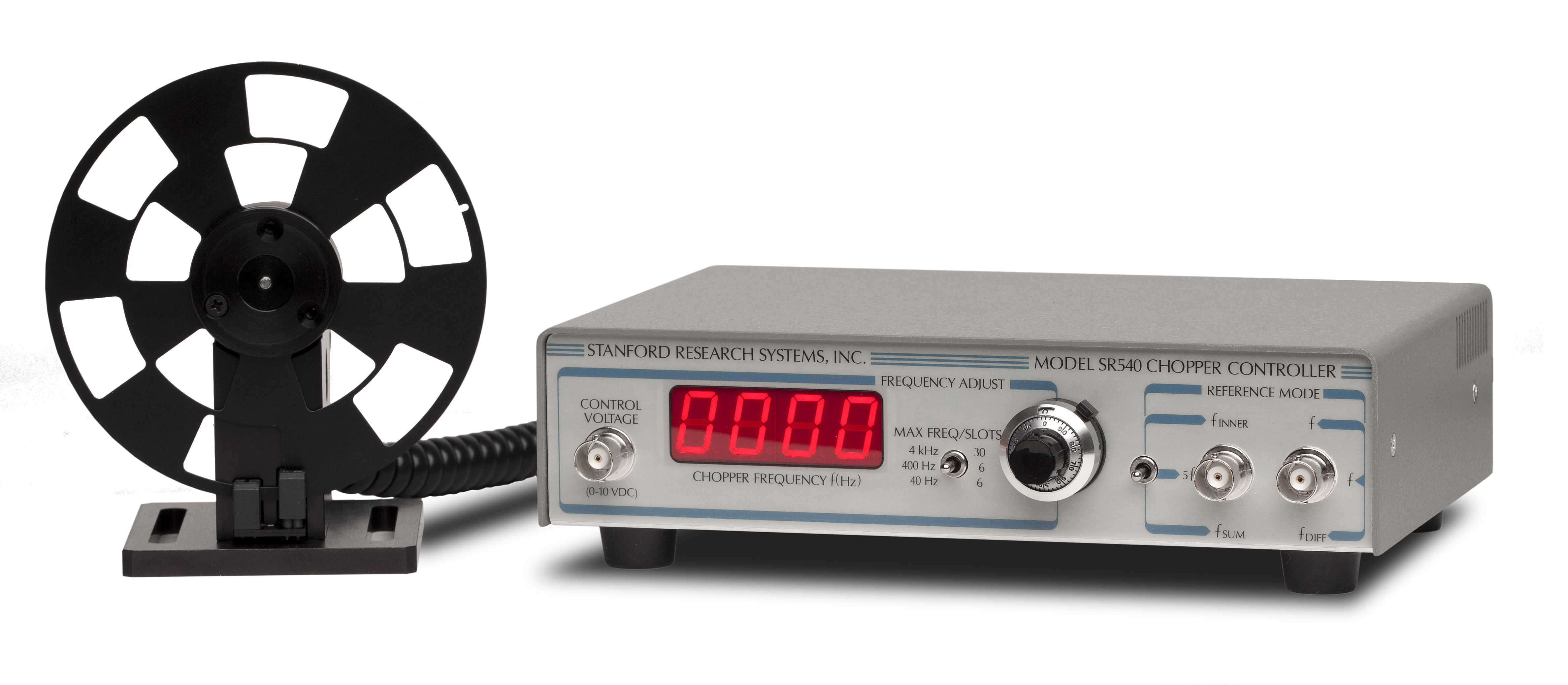
SR540 Optical Chopper

|
The SR540 chopper will handle all your optical chopping |
SR540 Optical Chopper
SR540 Optical Chopper
SR540
Single-Beam ExperimentSingle-Beam Experiment
|
The SR540 chopper will handle all your optical chopping
Optical Chopper Applications
In this application, a single optical beam is chopped by the outer row of slots, and the reference output from the right BNC is used to lock the
Dual-Beam ExperimentDual-Beam Experiment
|
In this arrangement, the output from a single source is split and chopped at two different frequencies by the two rows of chopper slots. One beam passes through the experiment while the other is used as a reference beam. The beams are recombined and sent to the same detector. Two
SR540 Specifications |
|
General |
|
| Chop frequency | 4 Hz to 400 Hz (5/6 slot blade) 400 Hz to 3.7 kHz (25/30 slot blade) |
| Frequency stability | 250 ppm/°C (typ.) |
| Frequency drift | <2 %, 100 Hz < f < 3700 Hz |
| Phase jitter (rms) | 0.2° (50 Hz to 400 Hz) 0.5° (400 Hz to 3.7 kHz) |
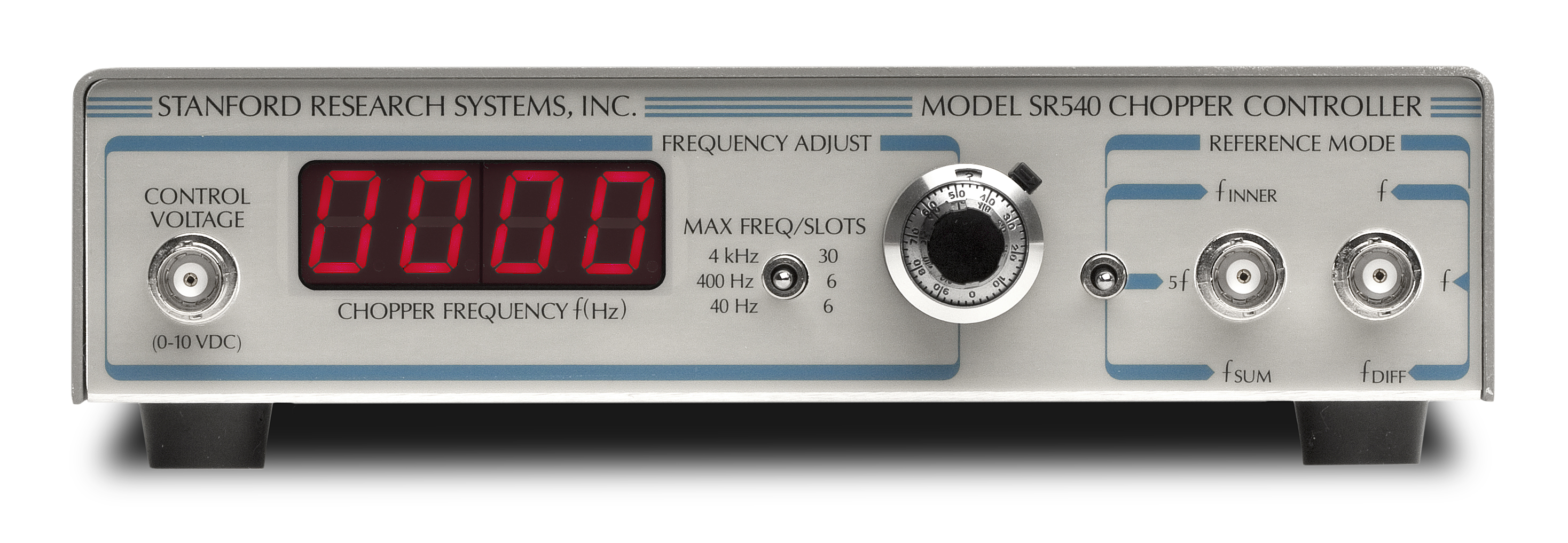
| Frequency display | 4-digit, 1 Hz resolution and accuracy |
| Frequency control | 10-turn pot with 3 ranges: 4 Hz to 40 Hz 40 Hz to 400 Hz 400 Hz to 3.7 kHz |
| Input control voltage | 0 to 10 VDC for 0 to 100% of full scale. Control voltage overrides frequency dial. |
| Reference modes | ƒinner, ƒouter, 5 × ƒouter, ƒinner + ƒouter, ƒouter - ƒinner |
| Dimensions | Controller: 7.7" × 1.8" × 5.1" (WHL) Chopper head: 2.8" × 2.1" × 1.0" (WHL) |
| Blade diameter | 4.04" ±0.002" |
| Cable length | 6 ft. |
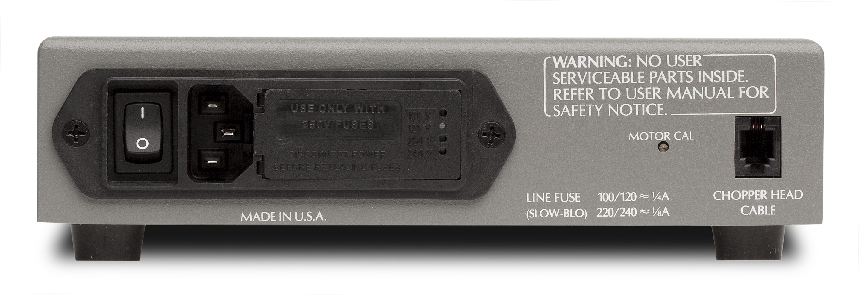
| Power | 12 W, 100/120/220/240 VAC, 50/60 Hz |
| Warranty | One year parts and labor on defects in materials and workmanship, 90 days on motor. |


