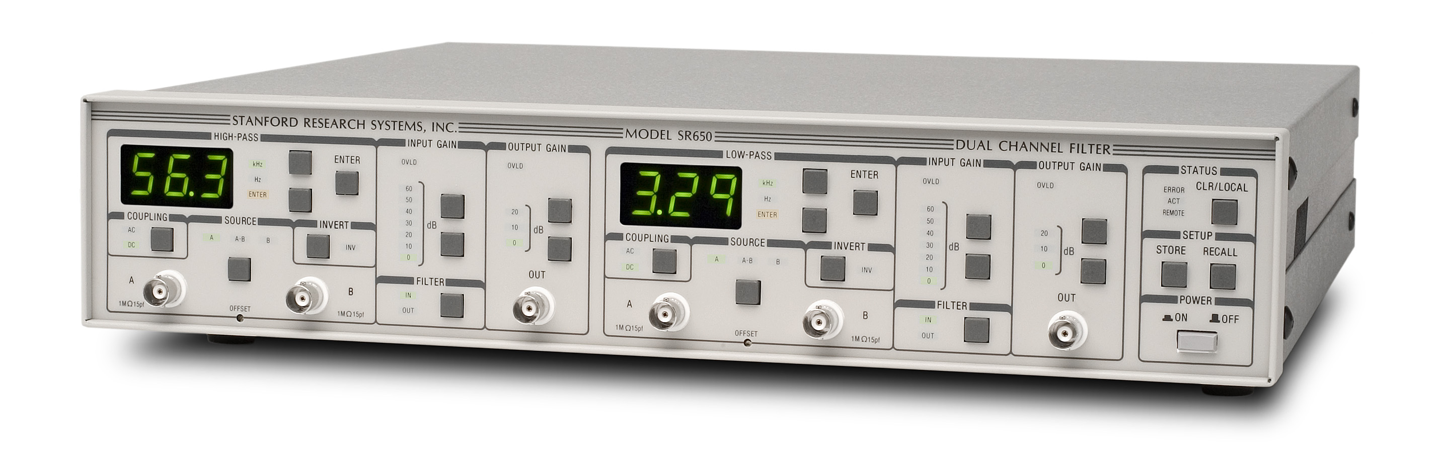
SR600 Series Programmable Filters
SR600 Series — Programmable Filters
The SR600 series consists of three dual-channel instruments. Each instrument channel has a low-noise preamplifier, a precision high-pass or low-pass filter section, and an output amplifier. The filters are 8-pole, 6-zero elliptic-type with 115 dB per octave rolloff, 0.1 dB of passband ripple (LPF), and 80 dB of stopband attenuation. Cutoff frequencies can be set between 1 Hz and 100 kHz making the SR600 Series ideal for applications including anti-aliasing, audio analysis, and frequency-domain signal conditioning.
Model - Configuration
SR640 — dual low-pass
SR645 — dual high-pass
SR650 — high-pass/low-pass
Inputs and Preamplifiers
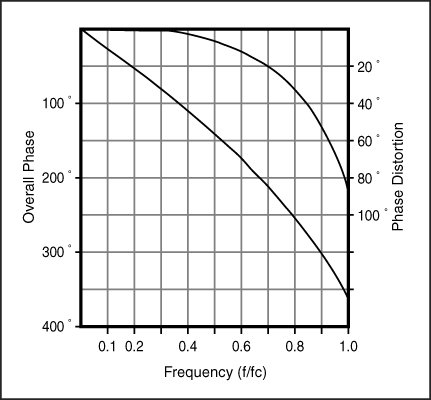
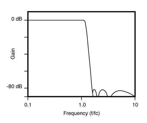
Phase Distortion
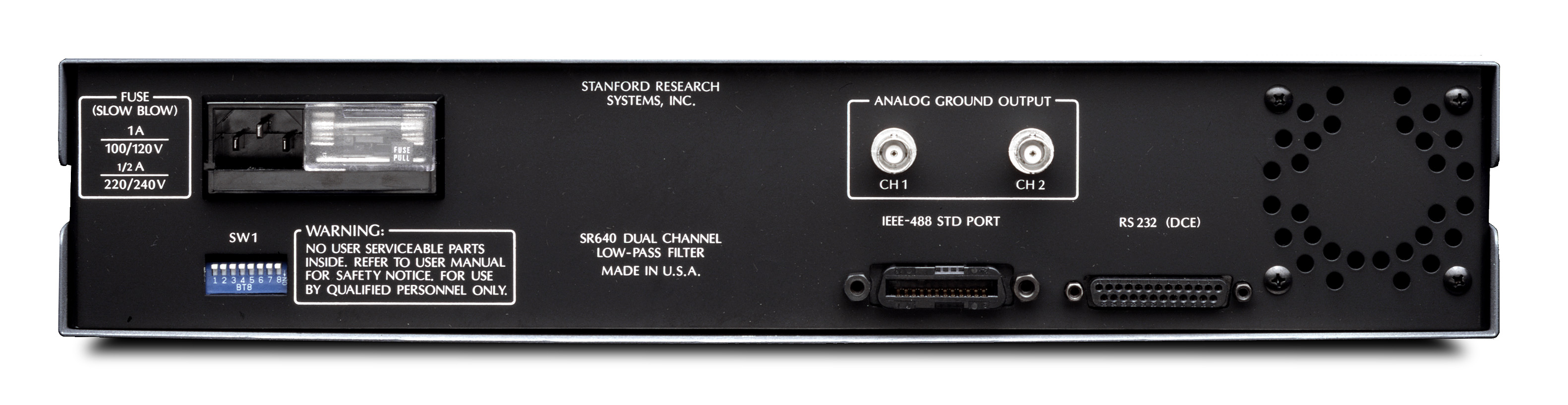
|
Each filter channel has a floating, differential input with 1 MΩ input impedance and 6 nV/√Hz of input noise. The analog ground for each filter channel is available at a rear-panel BNC connector to provide complete flexibility in grounding. The filter grounds may be tied to the instrument's chassis ground or to any other point. Both AC and DC input coupling can be selected, and an invert key allows the phase of the signal to be shifted by 180° with a single key press. Up to 60 dB of preamplifier gain can be specified in 10 dB increments. A simple offset adjust screw lets you null DC components in your signal.
Filter Characteristics
Filter characteristics for the SR600 series are shown below. The exact filter transfer function is given in the specifications section. (The graph shows the low pass response. The high pass response is found by inverting the curve around f=1.) The large amount of excess phase, typical of elliptical filters, makes the SR600 series filters optimum in frequency-domain applications. Note that the 0.1 dB passband ripple specification for the SR640 series filters is a measured specification, not just the theoretical passband ripple of the transfer function. Other filter characteristics include an attenuation slope of -115 dB/octave and a stopband attenuation of greater than 80 dB. Worst-case phase match between channels is better than ±0.75° from DC to 100 kHz, and improves to ±0.25° for cutoff frequencies below 10 kHz.
Post-Filter Gain and Bypassing
After the filter, another amplifier section provides up to 20 dB additional gain. The standard output drives loads of greater than 300 Ω at 10 Vpp, while the optional high-power output drives 10 Vpp into a 50 Ω load. Each filter may be independently bypassed from the front panel or from the computer interface. When bypassed, both the prefilter and postfilter gains remain active, and the resulting amplifier has a bandwidth of 450 kHz.
Programming
A key feature of the SR600 series is its programmability. Both GPIB and RS-232 interfaces are standard, and all instrument settings can be queried and changed via the interfaces. Cutoff frequencies can be changed in under 100 ms, making the SR600 series ideal for applications involving frequency-agile filters. Careful attention has been paid to minimizing noise resulting from the presence of the microprocessor and GPIB and RS-232 interfaces. Both the interface electronics and the instrument's microprocessor control circuitry are optically isolated from the filter sections in order to reduce digital-analog crosstalk. The CMOS microprocessor "sleeps" while the interface and front panel are inactive in order to reduce the amount of digital noise in the instrument.
Stored Settings
Up to nine complete instrument configurations, including amplifier gains and cutoff frequencies for both channels, can be stored in non-volatile memory for later recall. Settings can be recalled from the front panel or through the computer interfaces.