SR715 & SR720
The SR715 LCR and SR720 LCR Meters measure passive components with as little as 0.05 % error.
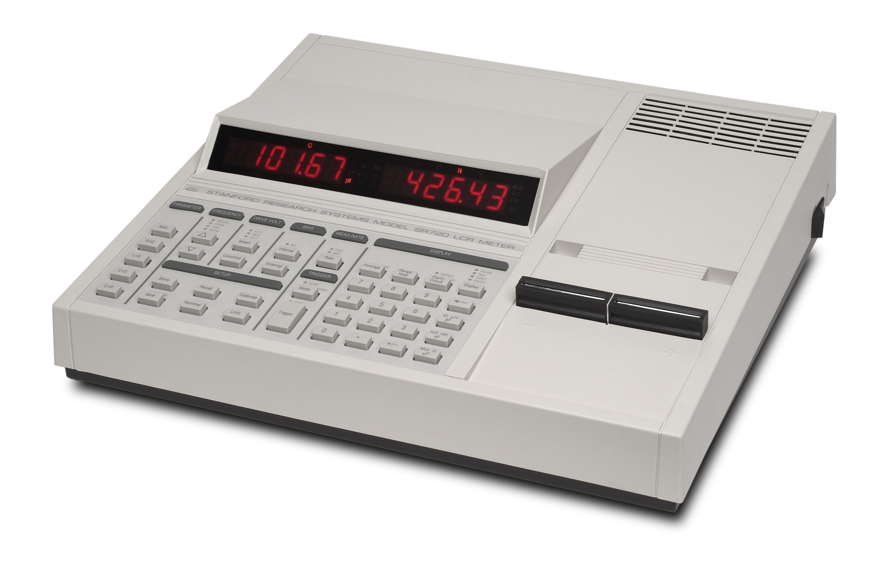
Front-Panel Display
A 5-digit LED display shows measured values, entered parameters, instrument status, and user messages. When making measurements, the major parameter (L, C or R) is shown on the left display and the appropriate minor parameter (Q, D or R) is shown on the right display.
Making Measurements
Measurements can be performed at test frequencies of 100 Hz, 120 Hz, 1 kHz, 10 kHz and 100 kHz (SR720 only).
Measurements are taken at rates of 2, 10 or 20 samples per second. Consecutive readings can be averaged between 2 and 10 times for increased accuracy. Both series or parallel equivalent circuit models of a component are supported. Capacitor measurements use either the internal 2.0 VDC bias or an external DC source of up to 40 volts.
Simple to Operate
The power and flexibility of the SR715/720 does not come at the expense of
Convenient Calibration
The SR715 and SR720 make it simple to compensate for lead impedance and stray fixture and cable capacitance. The null calibration procedure automatically corrects both open and short circuit parameters at all frequencies and all ranges.
Binning
The SR715 and SR720 have built-in features to aid in component sorting. This is especially useful for production testing, incoming inspection, device matching, or when you need to test multiple devices of similar value. The meters allow you to sort components into as many as ten different bins.
The SR715 and SR720 support three types of binning schemes: pass/fail, overlapping and sequential. Pass/Fail has only two bins; good parts and everything else. Overlapping (or nested) bins have one nominal value and are sorted into progressively larger bins (e.g., ±1 %, ±2 %, ±3 %). Sequential bins can have different nominal values, each separated by a percentage or a nominal value and asymmetrical limits. Binning parameters are also easily stored in non-volatile RAM for quick setup in production environments.
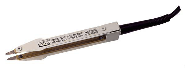
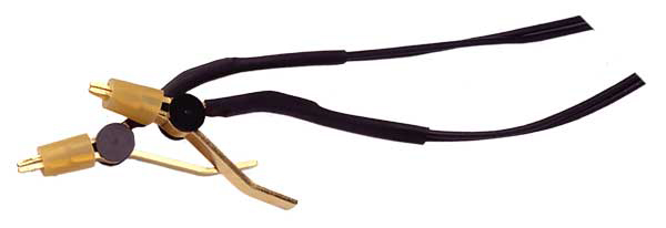
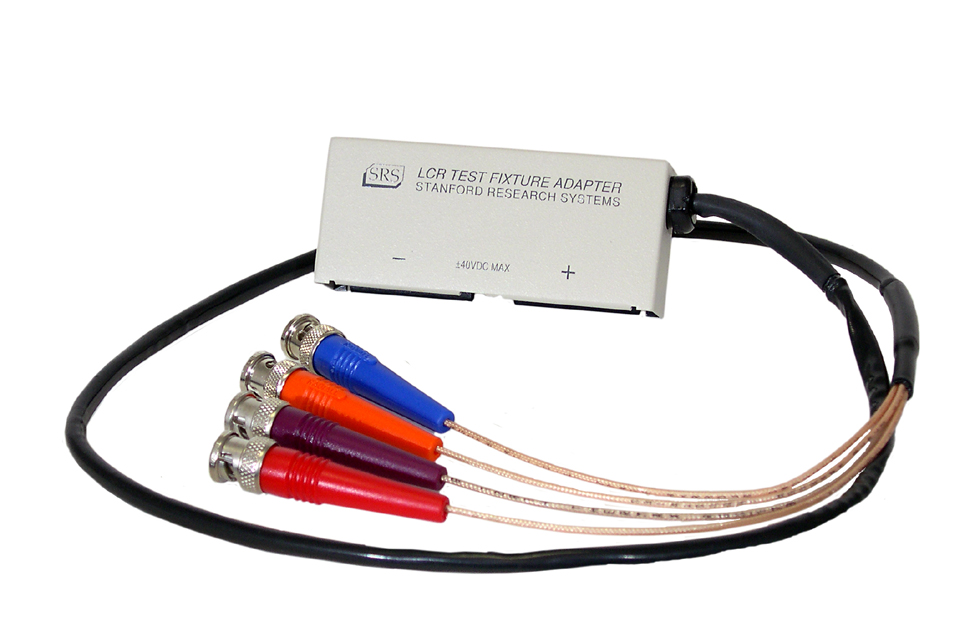
Test Fixtures
The SR715 and SR720 have a kelvin fixture which uses two wires to carry the test current and two independent wires to sense the voltage across the device under test. This prevents the voltage drop in the current carrying wires from affecting the voltage measurement. Radial components are simply inserted into the test fixture, one lead in each side. Axial devices require the use of the axial fixture adapters (provided).
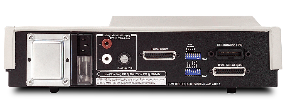
Rear Panel
Two rear-panel input connections are provided for an external bias voltage. Voltages as high as 40 VDC can be used. An optional handler interface provides control lines to a component handler for sorting. A standard