The SR865A Lock-In Amplifier offers superb performance and outstanding value. It's what you've come to expect from a Stanford Research Systems
With over 30 years of lock-in design experience SRS has made every effort to optimize each detail of the SR865A. From a hefty toroidal transformer that eliminates switch-mode noise to iOS connectivity that brings the lock-in to your cell phone to advanced DSP filters that eliminate more noise while speeding up your experiment, the SR865A is truly the ultimate
Lock-in performance starts at the front end. The SR865A front end offers both state-of-the art voltage and current input amplifiers. The voltage input is a switchable
The SR865A's built-in current amplifier represents a significant improvement over previous designs. The current input range is selectable from 1 μA or 10 nA. The 1 μA range has 400 kHz of bandwidth and
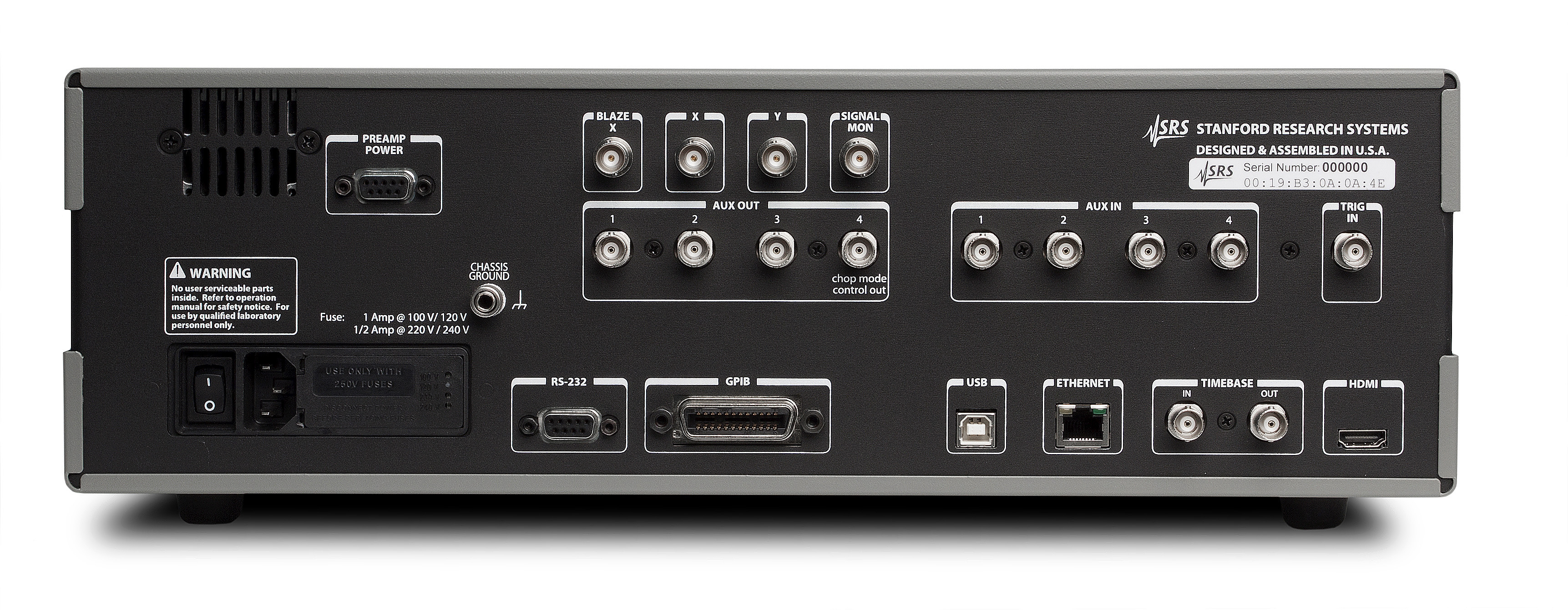
While the built in voltage and current amplifiers are suitable for most applications, the SR865A is also compatible with the complete range of specialized pre-amplifiers offered by SRS. The SR550 (FET input), SR552 (BJT input), SR554 (transformer input), SR555 (120 kHz current amp) and SR556 (low noise current amp) can all be powered directly from the SR865A's rear-panel preamp power port.
Sensitivity and Input Range
As with previous instruments, the Sensitivity setting of the SR865A is the voltage (or current) which produces a full scale output. But unlike previous designs, the input range of the SR865A can be explicitly set from the front panel without having to consult a confusing “dynamic reserve” equation. Simply choose the sensitivity required by your experiment and then select the smallest input range that doesn't overload. That's it.
The SR865A's effective dynamic reserve is simply the ratio of these two settings. For instance with a 10 nV sensitivity setting and a 300 mV input range the effective dynamic reserve of the SR865A is
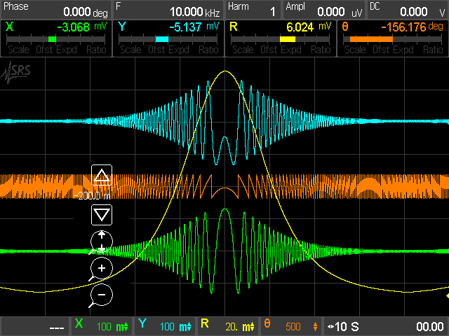
Output Time Constants
The SR865A offers traditional RC-response output time constants from 1 µs to 30 ks with rolloffs of 6, 12, 18, and 24 dB/oct. But in addition, the SR865A also offers advanced digital filters which can significantly reduce measurement time while increasing signal to noise. Below 3 s, the advanced filters are Gaussian FIR filters which at the same noise bandwidth as an RC filter have significantly better rise-time and stopband attenuation. These filters also have symmetric rise and fall profiles which preserves feature shapes while scanning in frequency. At time constants longer than 3 s, the advanced filters are linear phase IIR filters which settle nearly twice as fast as their RC counterparts for equivalent stopband attenuation.
Synchronous filtering may also be selected at reference frequencies below 4 kHz. The synchronous filter notches out multiples of the reference frequency and is extremely useful in making low frequency measurement where multiples of the reference frequency would otherwise show up in the
Reference Channel
The SR865A has a specified reference frequency range of 1 mHz to 4 MHz. Detection can be done at the fundamental of the reference frequency, or at up to the 99th harmonic. Several reference modes are available: Internal mode uses the SR865A's precision internal oscillator as the reference. External mode locks to an external sine or TTL signal. In Dual Mode, the lock-in detects at the difference frequency between the internally set reference frequency and an externally applied sync signal allowing direct recovery of a
Sine Output
The SR865A offers a precision sine wave output which can be set with 6 digits of frequency resolution and an amplitude range from 1 nV to 2 V. The SR865A output is unique in that it can be configured as a single-ended or as a differential (balanced) signal. A DC offset of up to ±5 V can be applied to the sine output. A rear-panel logic-level sync signal synchronized to the sine output is also provided.
Timebase
Rear-panel 10 MHz inputs and outputs are provided allowing the SR865A to be locked to an external frequency reference (such as the FS725 10 MHz Rubidium Frequency Standard). Alternatively, the 10 MHz output from the SR865A can be used to synchronize several lock-ins or other test equipment with a 10 MHz timebase input.
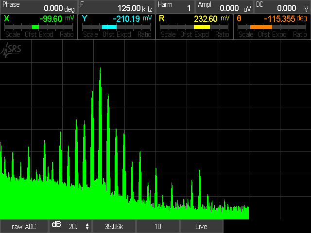
FFT Displays
Lock-in amplifiers are traditionally time-domain instruments but sometimes it's easier to understand a signal in the frequency domain. The SR865A is at home in both worlds. An FFT display shows the spectrum of the input signal at the front end, the post-mixer signal, or the spectrum of the signal after the
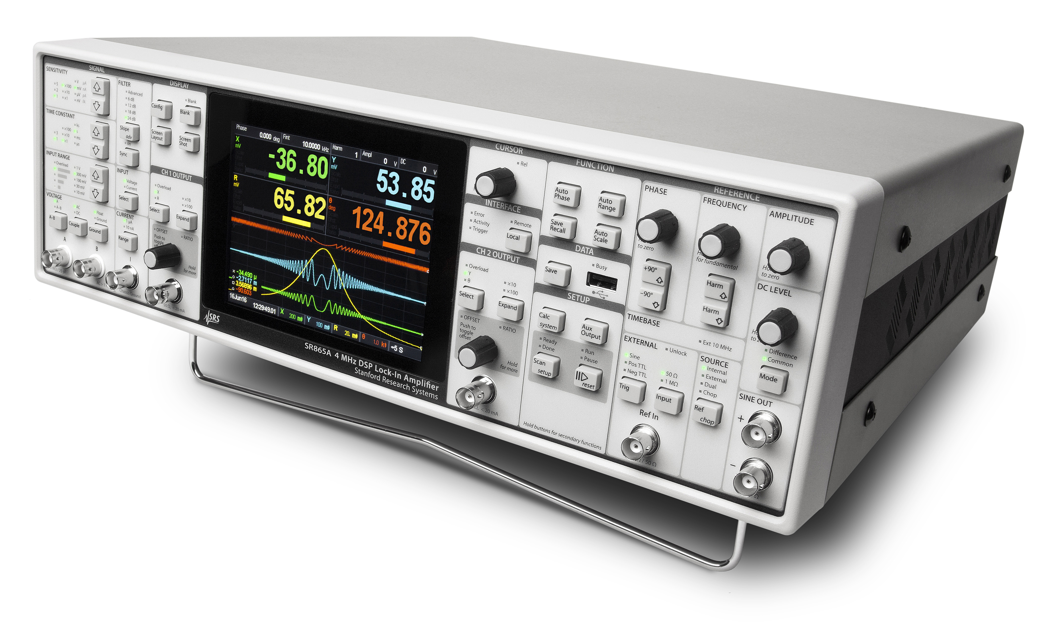
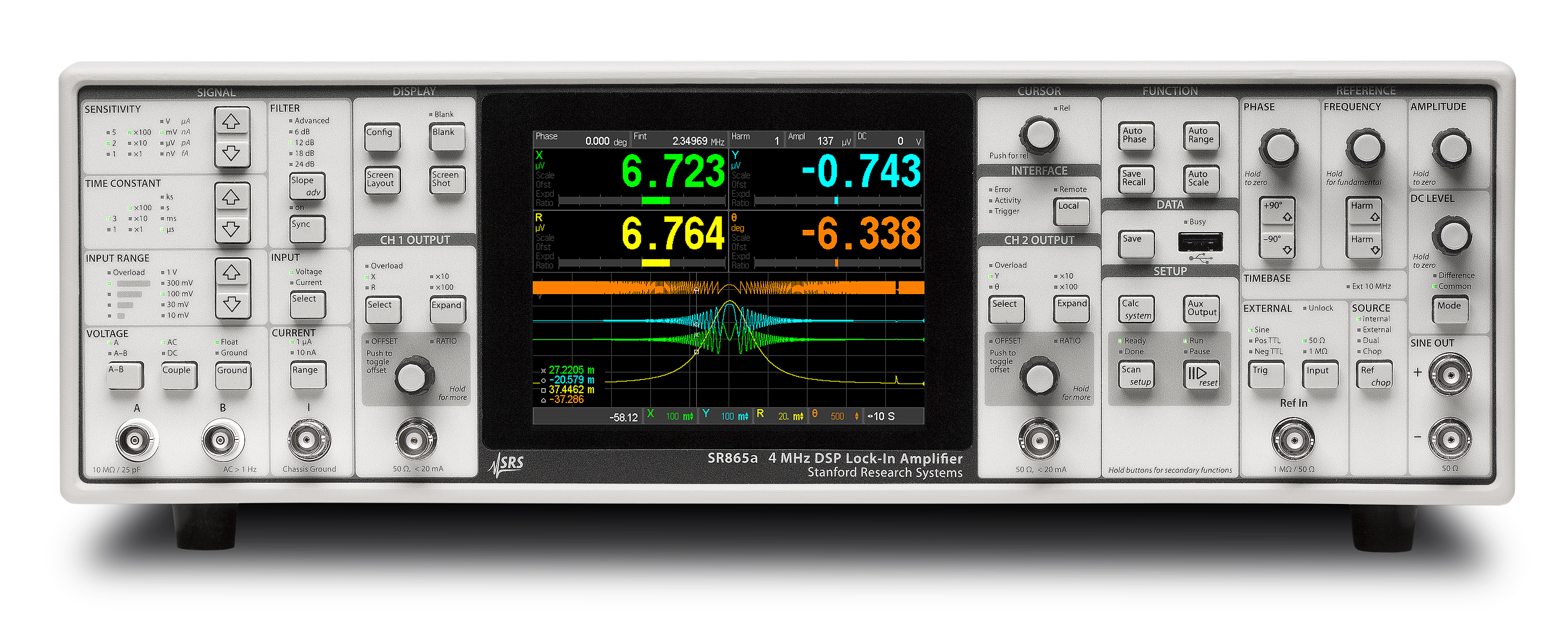
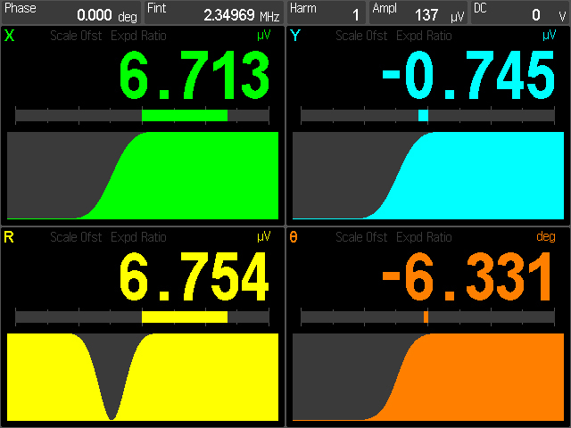
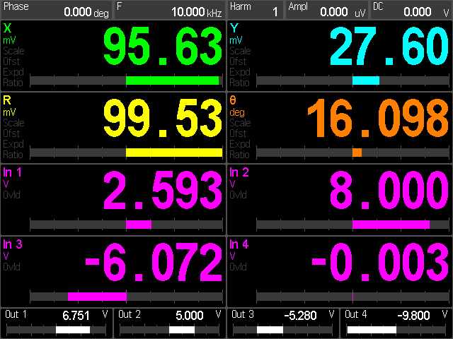
Front-Panel Touchscreen Display
The center of the SR865A's front panel is a full-color 640 × 480 touchscreen which can be set to display up to 4 channels of data. (When a dark lab is required, the LCD screen can be blanked from the front panel or from the remote interface.) Each data channel can be configured to display X, Y, R, Θ,
It should be emphasized that as useful as the touchscreen display is for displaying data, it's not necessary to use the touchscreen to control common instrument functions on the SR865A. All commonly used controls: time constant, reference frequency, sine amplitude and offset, input configuration, and more, are controllable with dedicated front panel knobs or buttons. Infrequently accessed configuration settings, such as the TCP/IP settings and other communication settings, are accessed through menus shown on the touchscreen.
Computer Connectivity
The SR865A comes standard with virtually every remote interface imaginable.
A front-panel USB port allows data and screen-shots to a USB flash drive. Data can be saved either as comma delimited files or MATLAB compatible .MAT files. Incorporating screen shots and data into reports or spreadsheets has never been easier.