SR250
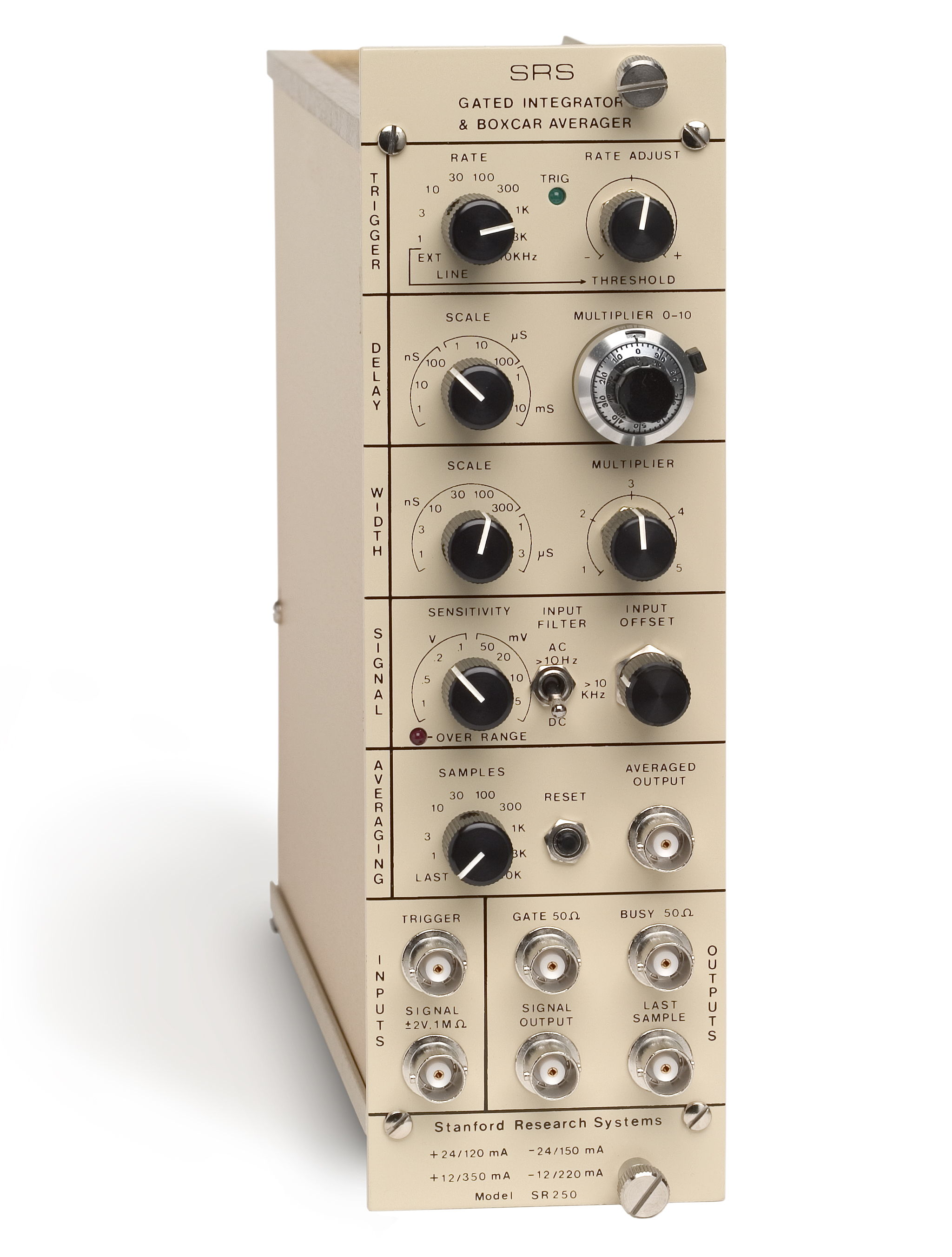
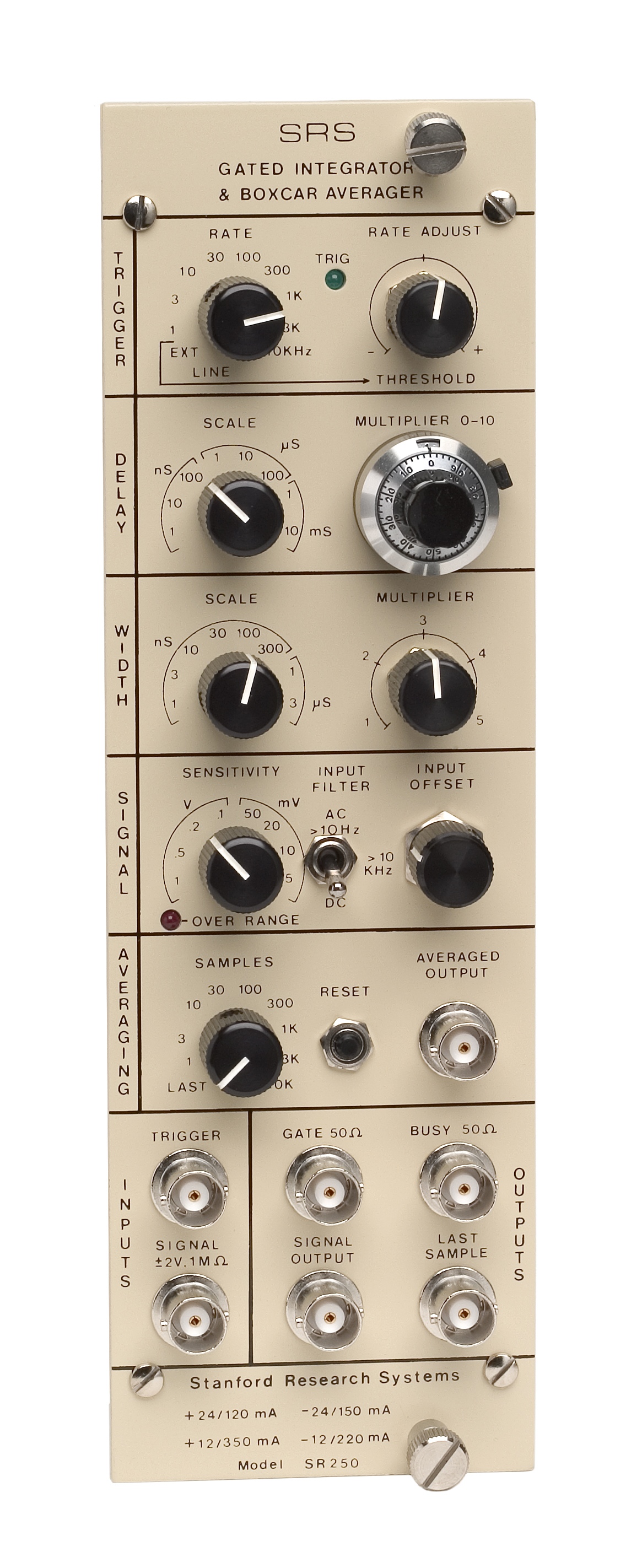
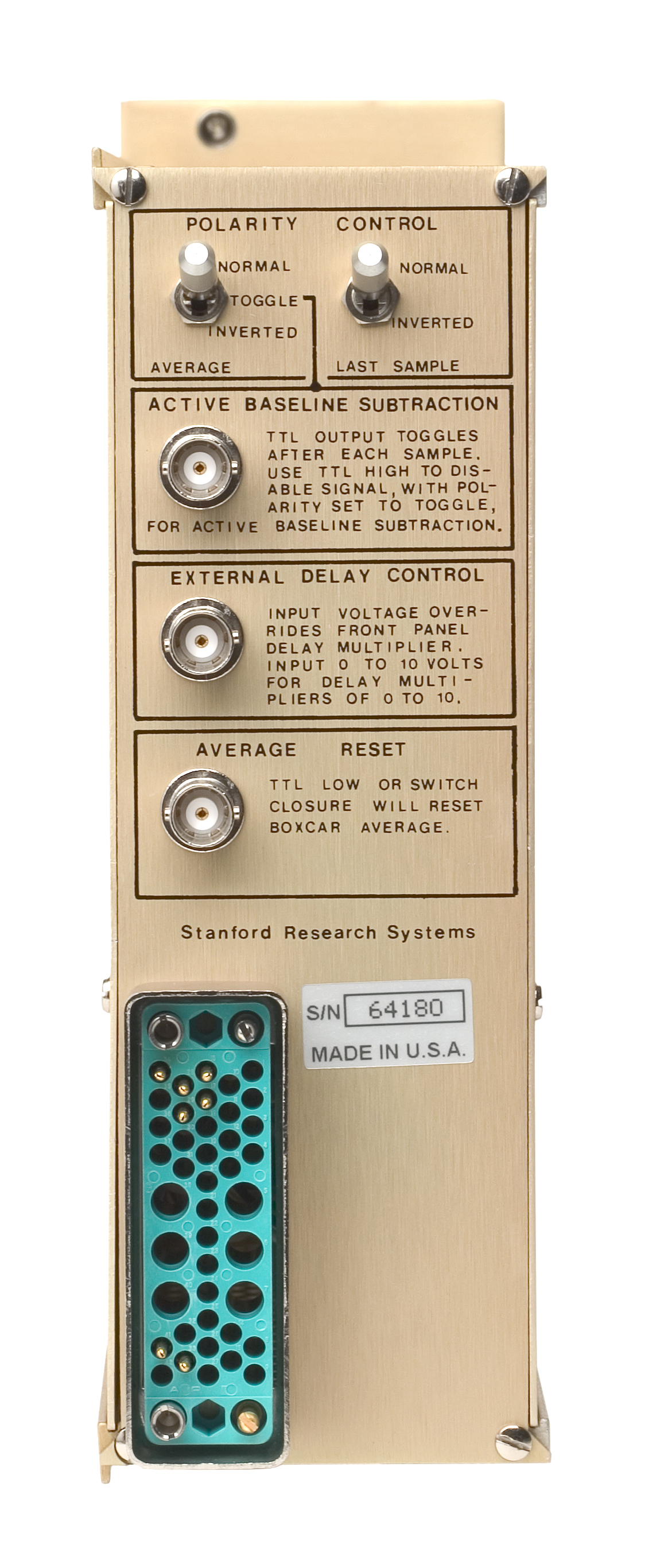
The SR250 Gated Integrator is a versatile, high-speed, NIM module designed to recover fast analog signals from noisy backgrounds. The SR250 consists of a gate generator, a fast gated integrator, and exponential averaging circuitry. The gate generator, triggered internally or externally, provides an adjustable delay from a few nanoseconds to 100 ms before it generates a continuously adjustable gate with a width between 2 ns and 15 µs. The gate delay can be set from the front panel or automatically scanned by applying a rear-panel control voltage. Scanning the gate allows the recovery of entire waveforms.
The fast gated integrator integrates the input signal during the gate. The output from the integrator is then normalized by the gate width to provide a voltage proportional to the average of the input signal during the sampling gate. This signal is further amplified and sampled by a
Triggering
The SR250 may be triggered internally or externally. The internal rate generator is continuously variable from 0.5 Hz to 20 kHz in nine ranges. The external trigger pulse may be as short as 5 ns, allowing the unit to be triggered with fast pulses from photodiodes and photomultipliers. Single shot and line triggering can also be selected.
Signal Inputs
The sensitivity of the instrument
Gate Timing
The delay of the sample gate from the trigger is set by the delay multiplier and scale. The delay scale is multiplied by the setting on the
The width of the sampling gate may be continuously adjusted from 2 ns to 15 µs over eight width ranges. A simple modification of the unit allows gate widths of up to 150 µs.
Signal Outputs
A moving exponential average of 1 to 10,000 samples can be selected from the front panel. This traditional averaging technique is useful for pulling small signals from noisy backgrounds. In the case of a random white noise background, the
Average Reset
The reset button sets the average output to zero. The average may also be reset by a rear-panel logic input. The average reset input will accept a TTL signal or a switch closure to ground to reset the moving average output.
Polarity Control and Active Baseline Subtraction
The polarity of the last sample and averaged outputs is controlled by rear-panel toggle switches. Positive outputs can be selected for negative signals, and vice versa, allowing easy interfacing with unipolar
Additional Outputs
The signal input is passed on to the signal output by a length of coaxial cable for termination and for gate timing. It is delayed exactly 3.5 ns from the input, and can be terminated to optimize either signal gain or response time. The gate output provides a pulse synchronized with the internal gate signal. The gate output is timed so that it can be overlayed with the signal output for precise adjustment of gate timing. The busy output provides a TTL timing pulse which is high while the unit is integrating, and goes low when the SR250 is ready to accept another trigger. These outputs help simplify experimental setup and troubleshooting.